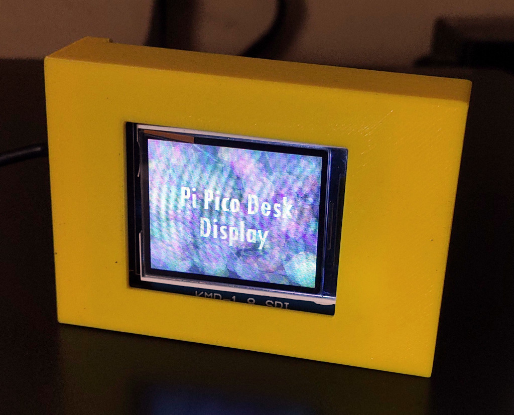
Do you ever wish having a programable display sitting on your desk showing off cool things like memes. This article will help you build just that. The idea is to create a customizable portable display, powered by a Raspberry Pi Pico that can be used in various ways.
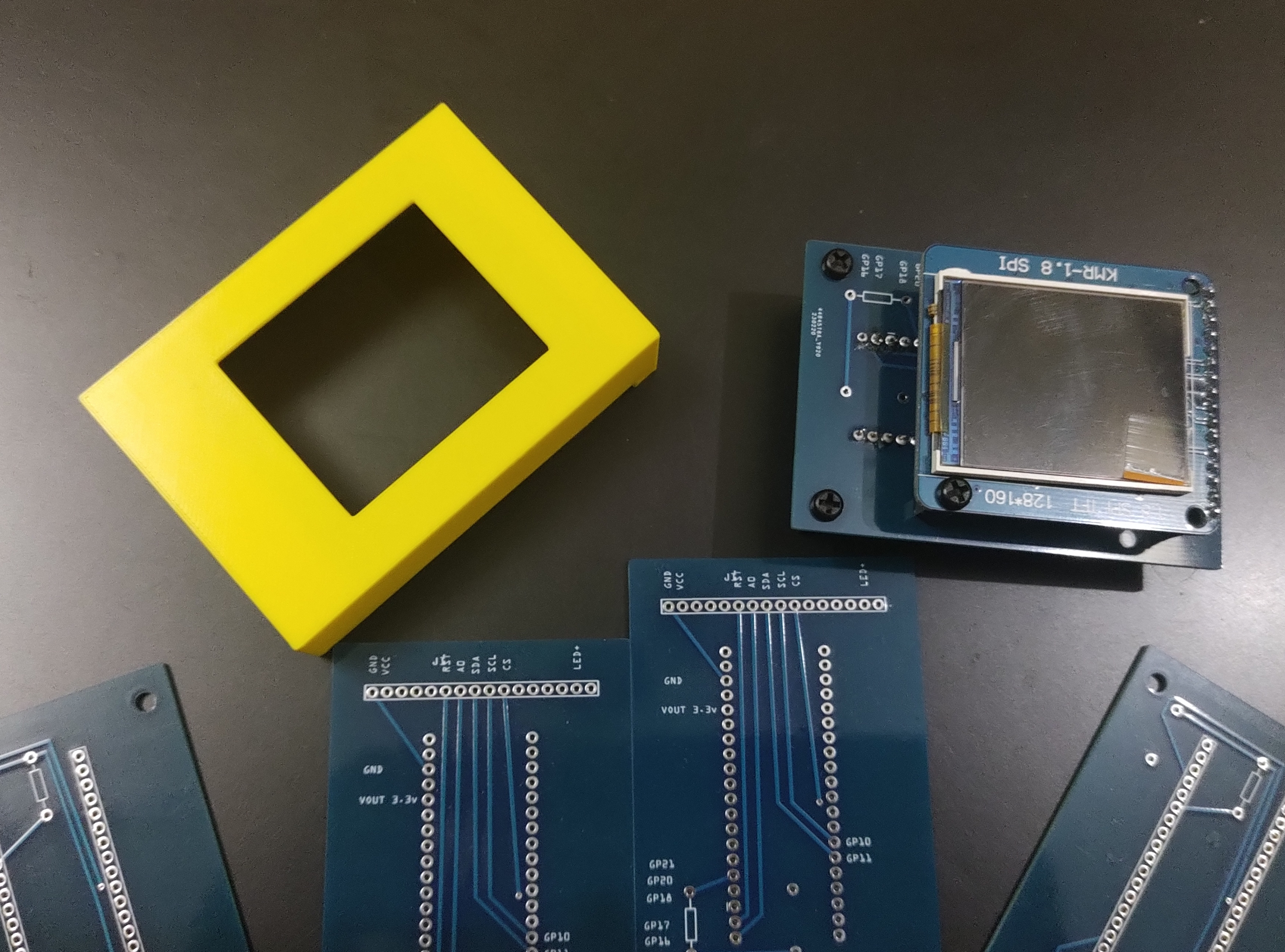
This is a tabletop hackable display made using Raspberry Pi Pico, 1.8 inch TFT LCD , a custom designed PCB and 3D printed case. It can be used in many fun ways. The schematics for the PCB and the 3D printed case have been made available by me under Creative Common License in the project’s Github repository: code2k13/pipico_desk_display
The idea was to create a cool gadget that can sit on your desk and show off some cool information. I have used Fritzing for creating the PCB, Tinkercad for designing the case and CircuitPython for programming the display. Many aspects of the project are configurable, which I will discuss during the assembly instructions.
⚠️Please note that fabricating the PCB and the case should only be done by those with sufficient expertise to verify and adjust the design as necessary. The PCB schematics and 3D designs are provided for your personal use and responsibility. I cannot be held accountable for any unexpected issues or damages that may arise from their use.
Requirements
- A Raspberry Pi Pico (both models should work)
- My custom PCB
- The 3D printed case
- 1.8 inch SPI TFT LCD
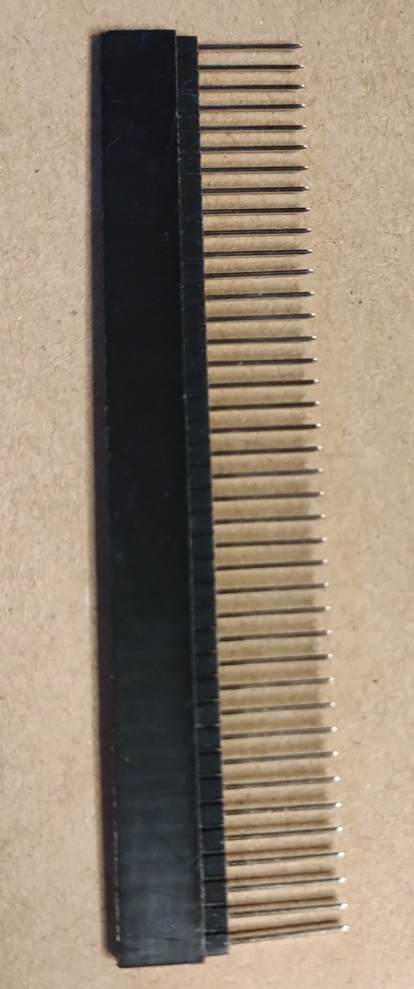
- Female headers (for soldering on PCB)
- Male Headers (or stackable female headers)
- M3 Spacers and screws
Assembling the PCB
Please ensure that your PCB thickness is less than 2mm. If not, you will have to modify the case’s design. I am yet to test this new case design.
Please verify if the case design will work with your PCB thickness before printing the case.
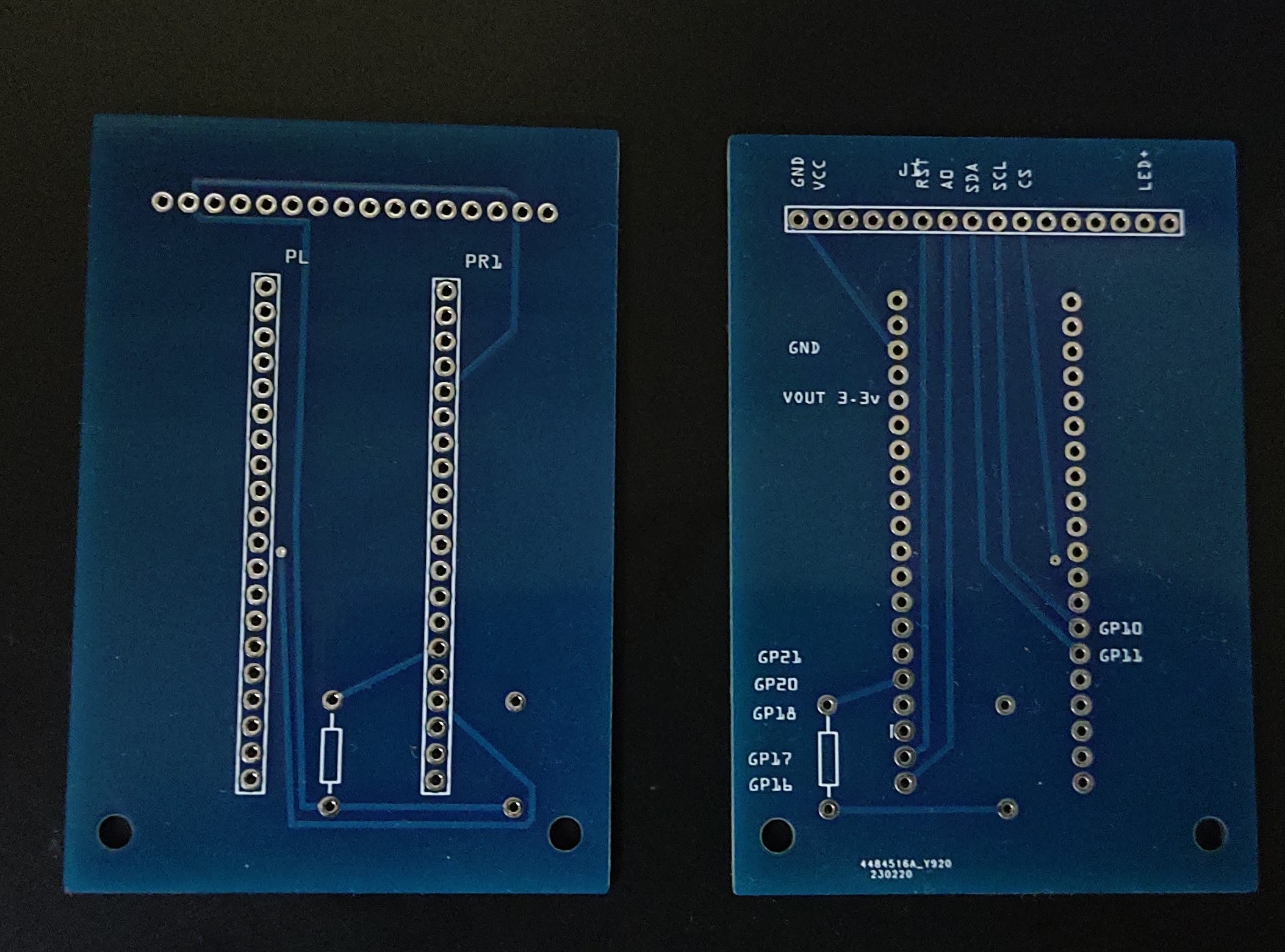
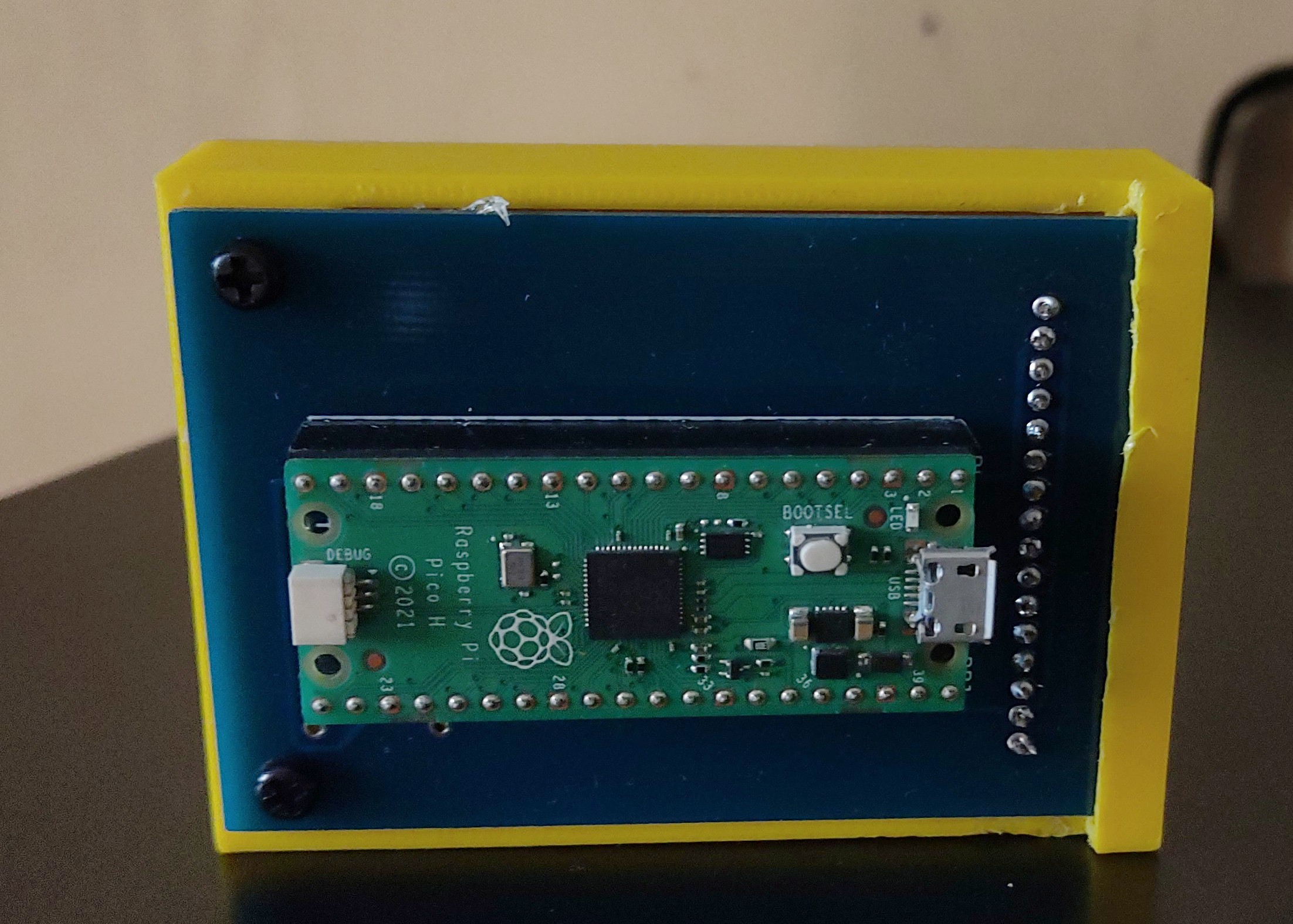
The project uses a custom dual layered PCB designed by me for standard through hole (2.54mm) components. I was able to get 5 PCBs fabricated locally for around $10 including shipping. The PCB houses two main components. The Raspberry Pi Pico on the back side and the LCD on the front. There is also provision to solder two pull-up resistors in case you plan to attach OV7670 camera to the board. This was needed by my ‘Handwritten Digit Recognition‘ project and some others which I have in mind. If you are not planning to use a camera in future, leave these slots empty.
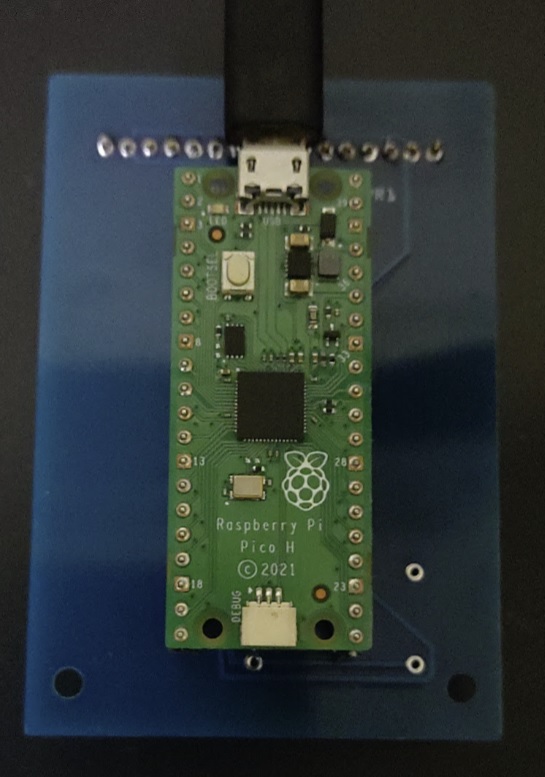
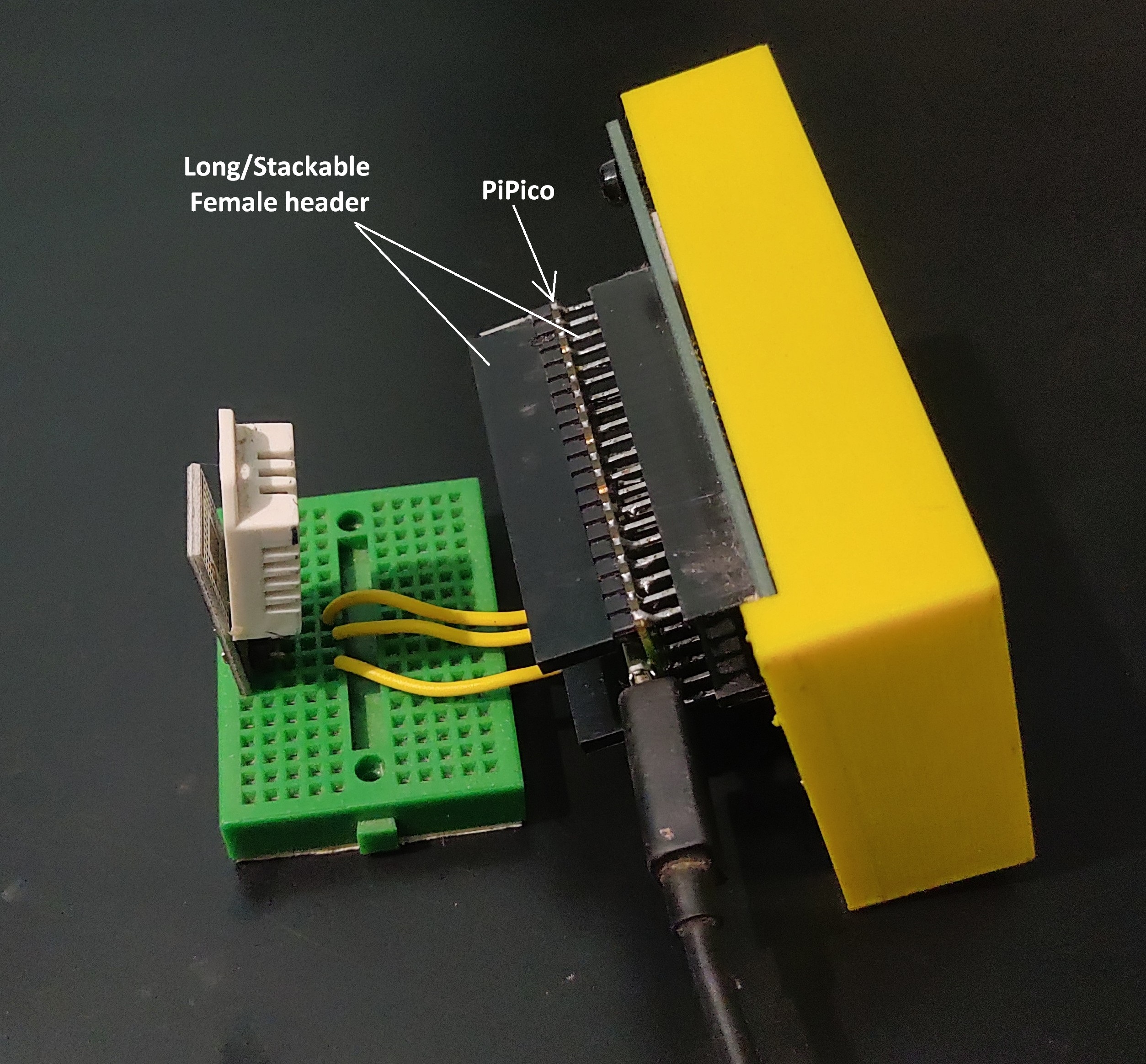
I recommend using female headers for connecting Pi Pico and the display (since most displays and Pi Picos come with male headers). However, if you do have a Pi Pico without headers, thing of using stackable (long) female headers to it, such that the bottom side of Pi Pico fits the female headers on the PCB and male headers are on the ‘BOOTSEL’ button side of the board. This opens up a lot of interesting possibilities and allows for connecting all sorts of sensors and peripherals to remaining pins of the Pi Pico. These are the connections on custom PCB:
| TFT Display Pin Number | TFT Display Pin Name | Pi Pico Pins |
|---|---|---|
| 2 | VCC | 3.3V |
| 1 | GND | GND |
| 10 | CS | GP18 |
| 6 | RESET | GP17 |
| 7 | A0 | GP16 |
| 8 | SDA | GP11 |
| 9 | SCL | GP10 |
| 15 | LED | 3.3V |
Optional connections
| Pi Pico Pins |
|---|
| Pull up resistor to GP21 |
| Pull up resistor to GP20 |
Rest of the pins are available for us (when using long/stackable headers on the Pi Pico).
Printing the case
⚠️DO NOT PRINT THE CASE BEFORE YOU READ THIS
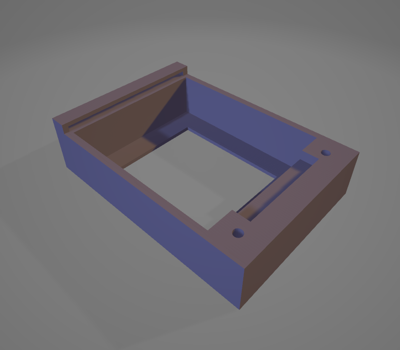
As shown in the above images, the case only covers the front part of the PCB. It has a rectangular hole for exposing the 1.8inch display. As you might have already seen, the case and the PCB have only two M3 holes. This is actually a mistake on my part when desiging the PCB. I tried to mitigate the mistake by adding a slit on one side of the case, so that you can fit one edge of the PCB in the slit and secure the other edge on the case using M3 holes on the case.
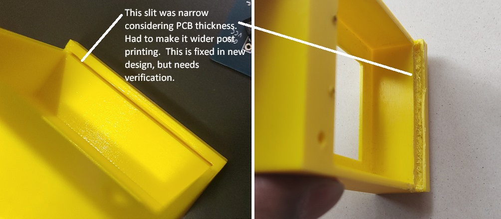
In the first version of the case, the slit was to narrow (0.8 mm), the PCB edge would not slide into it. It took me almost an hour and lot of meticulous carving to widen the slit and make the PCB fit as desired. In the new version of the case, I have made this slit 2mm wide.
⚠️Please ensure that your PCB thickness is less than 2mm. If not, you will have to modify the Tinkerkad design. I am yet to test this new case design.
Please verify if the case design will work with your PCB thickness before printing the case.
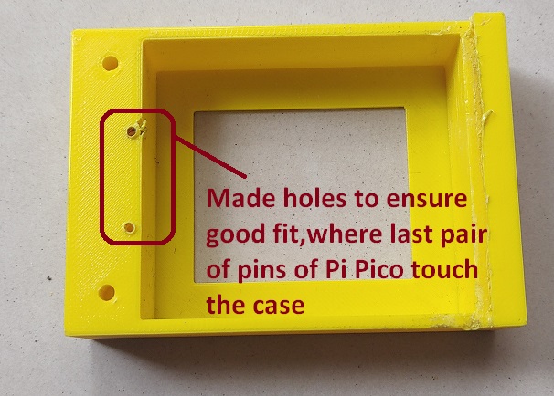
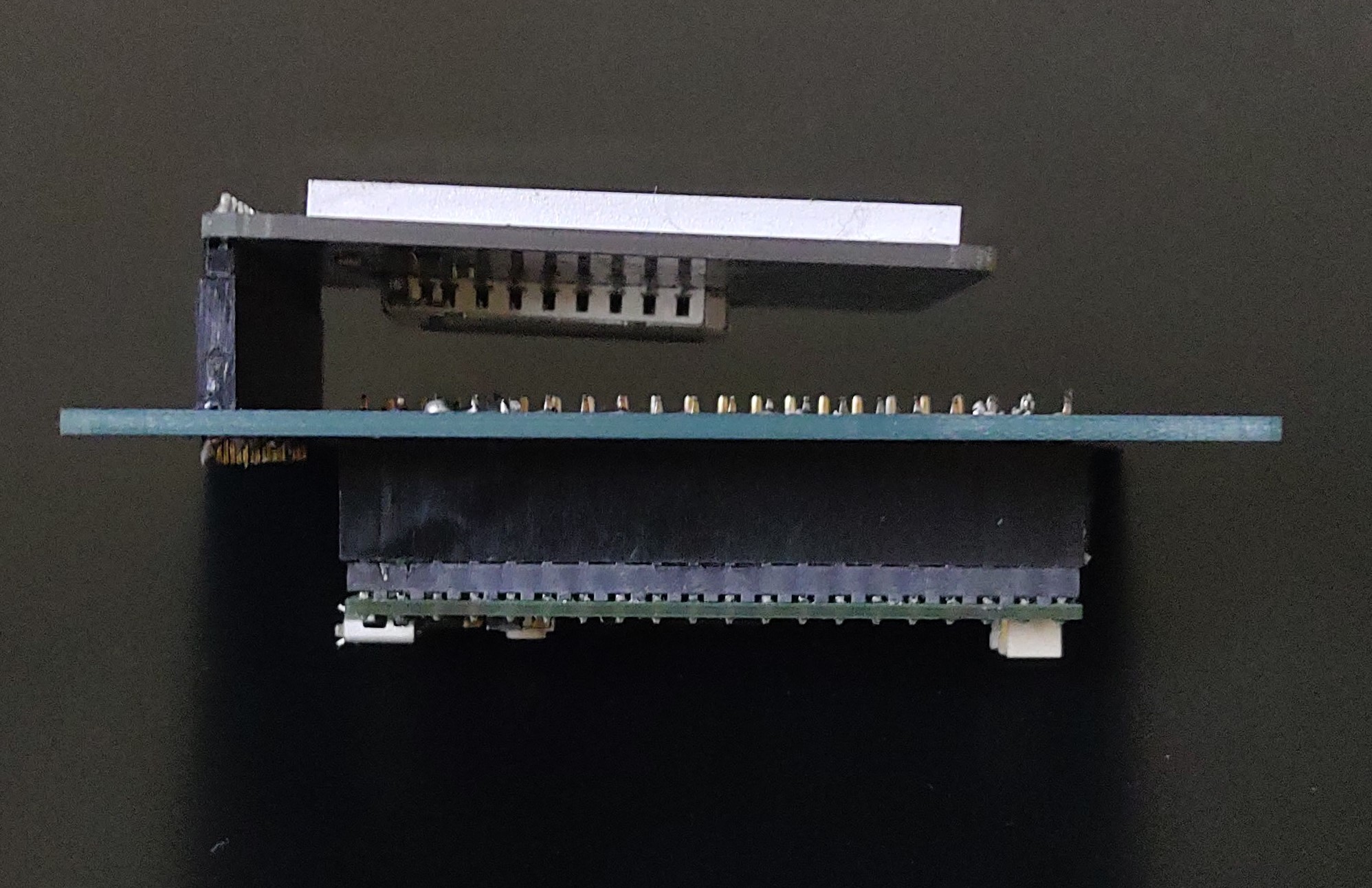
Another issue I observed was last pair of Pi Pico pins after soldering touched the plastic support bar on the right side of the case. I had to make holes under the pins to ensure a good fit and alignment of the PCB with M3 holes on the case.
You should put brass M3 threaded inserts inside the M3 holes of the case, before attempting to mount the PCB on the case using M3 screws or a spacers. You may be able to get away without using one, but highly recommend to use these inserts with the screws.
Another important thing is about ensuring that the display is not shaky. The display which I had had three M3 holes. I used a M3 screw , a spacer and some hot glue to stabilize and horizontally level the display against the board.
Assembling the project
I would suggest you the following steps:
- Print PCB schematics to scale on paper.
- Print top and bottom views of the case to scale on paper.
- Keep all the components on the printouts and understand how the final assembly will look like.
- First get the PCB fabricated.
- Get the project working by soldering Pi Pico and display on the PCB using headers.
- Check the thickness of the fabricated PCB and ensure that it will work with the slit mechanism of the case.
- Recommended that you have the slit bit wider than the PCB. It’s easier to add padding rather than widening the slit post printing.
- Print the case
- Make sure that the PCB fits on the back of the case and the M3 holes line up.
- Insert the M3 threaded inserts into the holes.
- Fit the PCB on the back side of the case. Use 6mm M3 screws to secure the PCB against the back side of the case.