In this article, I’ll share how I used a Raspberry Pi Pico, an OV7670 camera module, a 128x160 TFT LCD display and machine learning to build a handwritten digit classification system. This code is highly experimental. Even after you follow all the recommended steps in this article, some tinkering will still be necessary to get it to work. So buckle up and let’s start exploring!
Video of the project in action.
💡Link to project’s repository : https://github.com/code2k13/rpipico_digit_classification
Table of Contents
Our Goal
Required Hardware
Required Software
Wiring
Understanding OV7670’s image format
Postprocessing camera images
Training ML model
Exporting ML model Pico friendly format
Guidance on setting up the project
Troubleshooting
Future
Our Goal
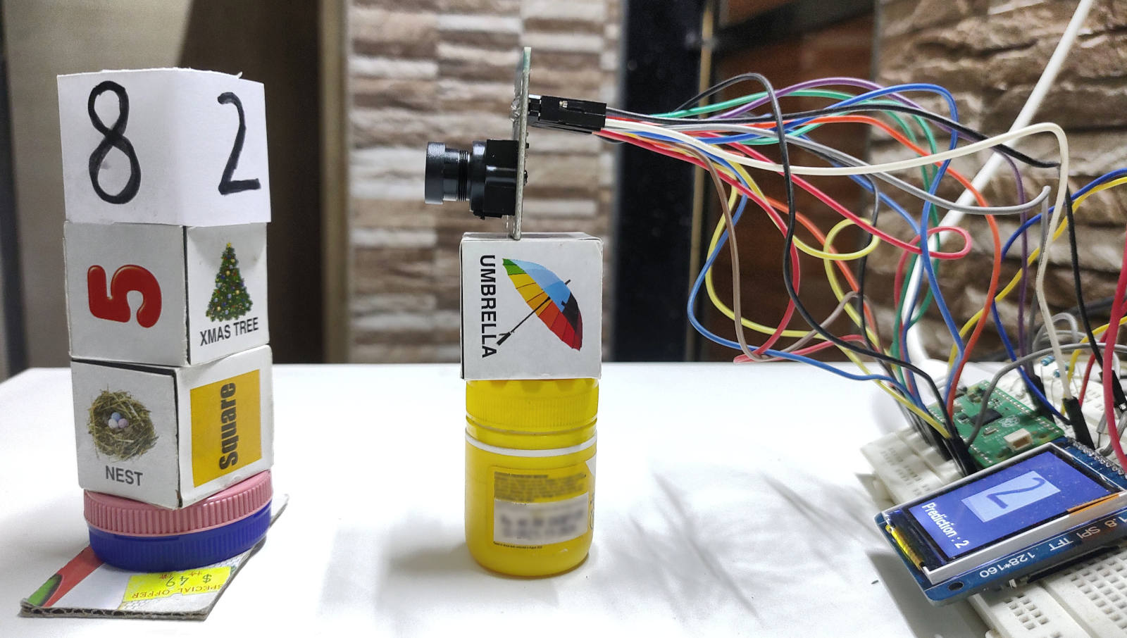
We intend to run a machine learning model on our Raspberry Pi Pico that analyzes photos received from a camera and tries to infer what digit was present in the image. An image of the project in action is shown below:
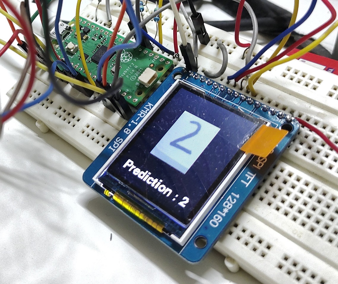
It is important to note that our machine learning model can be executed entirely on a Raspberry Pi Pico; a connected computer or cloud are not required. Therefore, creating compact machine learning models that fit in Pi Pico’s RAM and is accurate enough for our work is a major challenge we are aiming to overcome. This is no easy task. I will discuss this in more detail in a later part of this article.We also want to show our results on an LCD screen. So we use a 120x160 TFT LCD display to show the output to the user.
Lastly, everything needs to be done using CircuitPython. In my personal opinion CircuitPython is easy and fun to work with. The biggest advantage is your code will work with variety of 300+ boards supporting CircuitPython.
Required Hardware
Raspberry Pi Pico - This project has only been tested on the Raspberry Pi Pico. Hopefully, it won’t require any code modifications to run on the Raspberry Pi Pico W. As the code is written in CircuitPython, it is expected to work on most boards that support CircuitPython. Almost 80% of the GPIOs on the Pi Pico are used by the project, so make sure you have enough GPIOs on your board. You will need to change the code for the project to work with any other boards.
128x160 TFT LCD - similar to this one . Again, other options might be workable but may call for code changes. Theoretically, an LCD might not even be necessary; data could be written to a serial console instead. But practically speaking, this project might be difficult to implement without a LCD. The placement of the camera and the subject has a significant impact on the output. With an LCD, it is easy to align your handwritten numbers with the camera as you can constantly see what your camera is seeing.
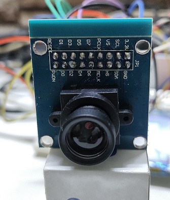
OV7670 Camera Module - I purchased this for Rs. 155 (approx USD 2), can you believe it ! Much cheaper than some color sensors !
Full sized breadboard (highly recommended)
Jumper Cables - May 20 each of M-F and M-M. There are lots of connections to be made !!
Required Software
Any text editor for editing the code if you plan to make any chances. A full Python distribution and pip for training and exporting the machine learning model. And off-course, lots of patience.
Wiring
There is a LOT of wiring that is required. Using breadboards and jumper cables is highly recommended.
The below table shows connections for the LCD
| Display Pin Number | Display Pin Name | Pi Pico Pins |
|---|---|---|
| 2 | VCC | 5V |
| 1 | GND | GND |
| 10 | CS | GP18 |
| 6 | RESET | GP17 |
| 7 | A0 | GP16 |
| 8 | SDA | GP11 |
| 9 | SCL | GP10 |
| 15 | LED | 3.3V |
The table below shows connections between OV7670 and PiPico
| OV7670 Pin name | Pi Pico Pin Name |
|---|---|
| D0 | GP0 |
| D1 | GP1 |
| D2 | GP2 |
| D3 | GP3 |
| D4 | GP4 |
| D5 | GP5 |
| D6 | GP6 |
| D7 | GP7 |
| PCLK | GP8 |
| MCLK | GP9 |
| HS | GP12 |
| VS | GP13 |
| PDWN | GP15 |
| RESET | GP14 |
| SCL | GP21 (via 4.7k external pull up resistor) |
| SDA | GP20 (via 4.7k external pull up resistor) |
Understanding OV7670s image format
Our camera can take images at various resolution and different formats. For sake of this example, we use the 60*80 resolution and RGB565_SWAPPED format.
cam.size = cam_size |
It is important to understand how every pixel is encoded. Each as a 16 bit integer and is stored in a format called as RGB656_SWAPPED. This means that
- Red component is captured using 5 bits
- Green component is captured using 6 bits
- Blue component with 5 bits
However first we need to ‘unswap‘ the pixel by doing:
pixel_val = ((pixel_val & 0x00FF)<<8) | ((25889 & 0xFF00) >> 8) |
Then we find individual components (red, blue and green) using the below code
r = (pixel_val & 0xF800)>>11 |
Once that is done we have to convert the pixel value to grayscale, because that is what our model expects. There are multiple ways to do this, but a simple average method works for us.
return (r+g+b)/128 |
Postprocessing camera images
Let’s spend a moment figuring out what processing we could require. The camera captures 60x80 resolution RGB photos. This image can be made into a 60x80 grayscale using the code above. However, our model only accepts grayscale images that are 12x12. Therefore, we must first trim the image to 60x60 before resizing it to 12x12.
temp_bmp = displayio.Bitmap(cam_height, cam_height, 65536) |
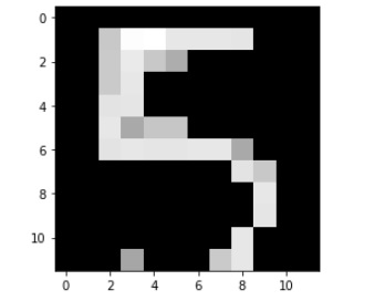
After extensive testing, I also discovered that photos can contain considerable noise for a number of reasons. This little thresholding function does a great job of improving our prediction:
input_data = [] |
Given are images, the first one is without the thresholding code and second one is with thresholding. This is how our post-processed image which is sent to the ML model looks like:
Training ML model
You will most likely encounter the terms “nerual networks” and “convolutional neural networks” if you read research on image classification using machine learning, and this is very appropriate. When it comes to utilising machine learning to process images, convolutional neural networks are the gold standard. The do an excellent job with pictures. However, the issue with neural networks in general is that they are complex, require strong number-crunching technology, and require a respectable amount of memory to operate. It can be quite difficult to adapt a neural network to operate on a tiny microcontroller like the RP2040. For some leading edge work in this area, you should probably check out TFLite mini.
There are other machine learning (ML) methodologies that we may use that, while obviously giving less accuracy and reliability, are still obviously simple enough to function on microcontrollers. One of them is a support vector machine (SVM). It is a method of supervised learning that performs well with high dimensional data. We will utilise the “LinearSVM” implementation of this technique available in the scikit-learn Python package.
Given that this is a supervised learning problem, training data is required. Here, we’ll just train our model using the MNIST handwritten digit dataset that comes with scikit-learn. The model is trained using the code below (and needs to be run on a computer running normal Python distribution)
img_data = np.asarray(image_ds) |
I would strongly advise training and exporting the model using the Python notebook from this project’s repository (explained in next section). Here is the link to the notebook on Kaggle: https://www.kaggle.com/finalepoch/handwritten-digit-classification-on-pi-pico
Exporting ML model to Pico friendly format
The model we developed in the previous section can only be used with the scikit-learn package and a standard Python installation. The model cannot be run on our Pi Pico using CircuitPython. Therefore, we must export the model in a format that Pi Pico can understand. We intend to make our model as compact as possible because Pi Pico has a little amount of RAM. I decided to utilize an input image size of 12x12 pixels for this reason because I discovered it worked best with my setup.
Fortunately, there is an open source tool called m2cgen that can translate our learned scikit-learn model into “pure python” code which CircuitPython can run. Depending on the model architecture and hyper-parameters, this tool can produce rather large files. To reduce the size of the Python code, we use another tool called python-minimizer.
We can generate a minimized python file containing our model using these two commands
pip install m2cgen |
code = m2c.export_to_python(clf) |
python-minimizer svm.py -o svm_min.py |
Guidance on setting up the project
For guidance on running the code and software dependencies refer to project’s repository.
Link to project’s repository : https://github.com/code2k13/rpipico_digit_classification
An image of the setup I use for my experiments is shown below. Make sure the subject and the camera are at the same height. The LCD display aids in lining up the camera and the handwritten digit. For the approach to function, it is crucial to have good lighting, perfect alignment, and stability.
Troubleshooting
Check if your LCD is displaying output from camera properly. The camera module has a plastic lens cover, be sure to remove it.
Check if your camera is focussed properly. The OV7670 needs to be focussed manually by gently rotating the lens assembly.
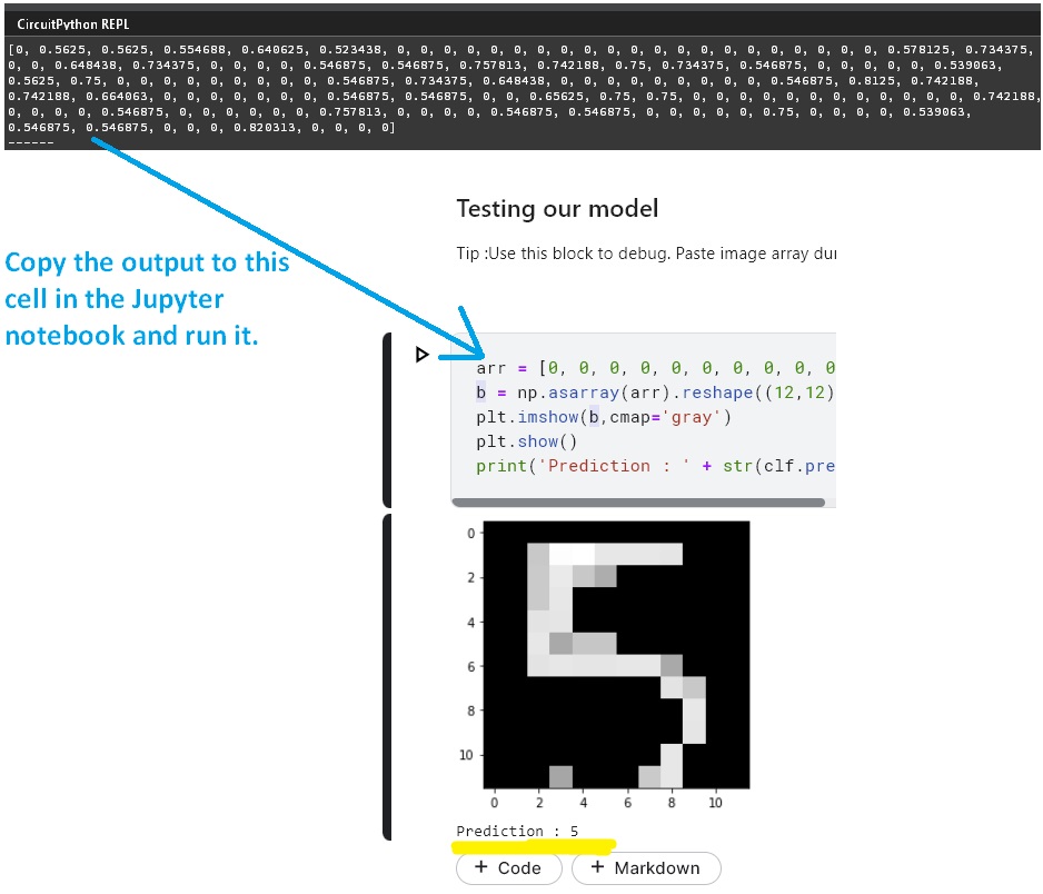
Uncomment the line below ‘#Uncomment these lines for debugging‘ in code.py, this will make the board output image matrix being sent to ML model. You can simply copy the array and use the Kaggle Notebook’s ‘Testing our model‘ section to visualize the image and check prediction for it using standard Python distribution. Play around with thresholding code if necessary.
The model is very sensitive to size of digits need to be right sized. Make sure that your handwritten digits fit the whole display frame in the LCD display. On the LCD display you should see the full digit in black on a pure white background.
My experiments suggest that using the digit ‘8’ to calibrate settings alignment gives great results.
Ensure you have proper lightning.
Future
There are several experiments one could do even with such a simple project like this. Some of the ideas I plan to work on in future :
- Training the model using data obtained from camera.
- Good memory management in code and thus enabling larger image sizes.
- Train the model on some other fun dataset (shapes, sings ,patterns).
- Convert the whole thing to ‘C/C++’ (using Pi Pico SDK and TFLite micro)