Someone rightly said ,
“A picture is worth a thousand words” !
In the electronics world we can say this translates to,
“ A display is worth a thousand LEDs”.
I have always wanted to add some sort of display to my microcontroller projects. The main issues I faced with this were:
- The most common LCD is 16x2 character display, which is large in size, heavy and needs lots of pins for interfacing. Also it does not support graphics (in short , ‘not so cool’).
- Your microcontroller needs to have a library to support the display and necessary I/O pins. I know Arduino has both, but something like ATTiny85 will struggle. Even with an ATMega you quickly run out of PINs after interfacing most displays.
- I don’t like the idea of adding a breakout board or a shield just to support a display.
- Cost and availability are always a problem (If you live in US/Europe, you are lucky :-) )
Meet the supercool OLED display !
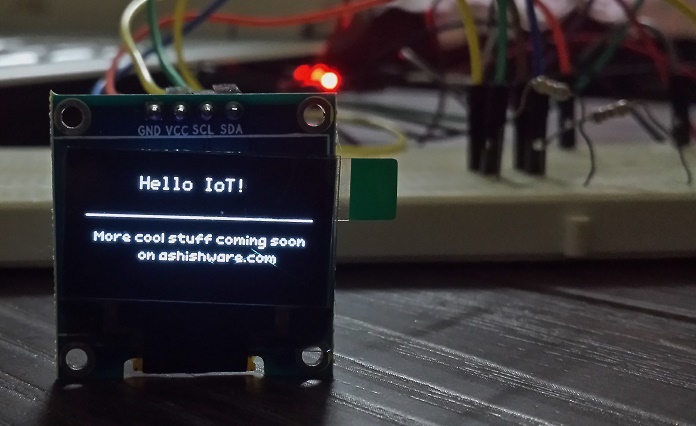
Recently, I was doing a project using standalone ESP8266 and wanted to add a display to it. I have discussed about ESP8266 before on my website and I’ll say this again: “At times, I find it more interesting than Arduino”. I have the most common (and cheap) type of ESP8266 module which exposes only 2 GPIO pins. Initially, I was thinking of adding a microcontroller to my project so that I can interface a display. After some research on the internet , I came across this 128x64 pixel monochrome OLED display. It is tiny and supercool, because:
- Cost is around USD 9 (in India), which is OK.
- OLED, so no backlight required, self illuminating.
- Can be controlled with just 2 pins (using I2C bus protocol).
- Lightweight, tiny and has low power consumption.
- Operates on 3.3v, so can be directly interfaced with ESP8266.
- Supports graphics ! NodeMCU has built in support for such displays.
So, I dropped the idea to use a microcontroller and promptly ordered this. I2C is a nice little bus protocol which I was not aware of until now. The best part about it is , it requires only two PINS (GPIOs will do) and multiple devices can be attached to a single I2C bus.
The hardware part
I have covered the process of flashing ESP8266 with NodeMCU firmware in my previous article , so I am skipping that part. I am assuming that you already have a ESP8266 with NodeMCU firmware. Given below is the circuit diagram. One thing to note is, I have added pull-up resistors (R1 and R2) to be on safe side. My research suggests that OLED display has internal pull-ups , but I was not willing to experiment. The recommended value of pull-up resistors is 4.7KOhm, but I had couple of 6.8KOhm ones lying around, so decided to use those. Please check the PINs on your OLED display. Many displays will have more PINs (compared to mine) to support SPI. Mine had only 4 pins, so connections were straightforward.
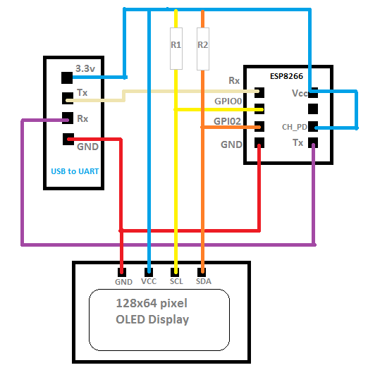
Summary of connections:
| ESP8266 PIN | Connected to: |
|---|---|
| VCC | To 3.3v PIN of UART and OLED display. |
| GND | GND of UART bridge and of OLED display. |
| TX | RX |
| RX | TX |
| CH_PD | 3.3v |
| GPIO 0 | SCL Pin of the OLED display. Also pulled-up to VCC using 4.7KOhm resistor |
| GPIO 1 | SDA Pin of the OLED display. Also pulled-up to VCC using 4.7KOhm resistor |
Important
Most USB to serial adapters support 5v. If you apply 5v to VCC pin of the ESP8266 module it will get damaged permanently. I can tell this from my experience :-) . So please ensure that your serial converter is 3.3v compatible. You can get a serial converter which supports both, 5v and 3.3v pretty cheap.
The software part
Given below is LUA code to display some text on the display. The code is fairly straightforward. It first initializes I2C on GPIO0 and GPIO2, then uses U8glib library bindings available in NodeMCU to draw some text. I will cover U8glib in more detail in my next article. To send the code to ESP8266, use luatool as explained in my previous article .
|
Conclusion
It is fascinating to see how technology is evolving day by day. In just under USD 10-15 , we have a wifi enabled device with cool little display. I’ll write more on this pretty soon. Until then, feel free to make and experiment.