After playing with my Freeduino kit for some time, I was surprised with number of things my Freeduino board could handle. So I decided to put all my components which I received with the kit permenantely on a single PCB and say good bye to my bread board. My goals were to:
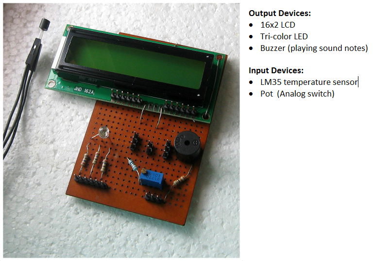
- Create a low cost board which incoprorates an LCD, temperature sensor, RGB led and buzzer.
- These are more than enough components for begineers to start writing some very interesting programs.
- It should be easy to construct for amatures like me!
- All features/components should be usable seperately.This increases re-usability of the board
The result is here:
What you need
If you are wondering why I didn’t try to create a sheild, let me confess, that my soldering skills are too poor to do anything of that sort. Also, attaching the LCD on a sheild would have been problematic. I have used some of the most common components to create this board. Please feel free to use your own judegement while picking up components. Many ompoents are part of that generally come along with kits. You may have to change the schematics based on your selection: I have reffered to Arduino or Freeduino as ‘main board’ in below section. All connections between main board and my board have been made using jumper wires.
Disclaimer
Author is not responsible for any damage/harm of any kind which may be caused by following this article. This article is just for guidance. Follow it at your own risk! Also, please take adequate precautions while handling soldering iron and power sources. I make no claims that the schematics described below are perfect and fool-proof. Connecting electronic components incorrectly can cause damage to the components as well as your main board.
General Saftey Instructions
General Saftey Instructions: Connecting electronic components incorrectly can cause damage to the components as well as your main board. Also, please take adequate precautions while handling soldering iron and power sources. I make no claims that the schematics described below are perfect and fool-proof.
List of components:
- 16x2 LCD (compatible with the Hitachi HD44780 driver)
- Break away headers (female in case your Arduino or Freeuino board has male connectors, else male)
- Jumper wires x 25 (male if you used female headers, else female)
- RGB LED (The one I used is common anode).
- 270 omh resistors x 3
- Buzzer and suitable resistor for connecting in series
- 1K ohm resistor
- Pot 3296 or smaller range one. (http://www.bourns.com/pdfs/3296.pdf)
- Normal Soldering stuff.
Schematics
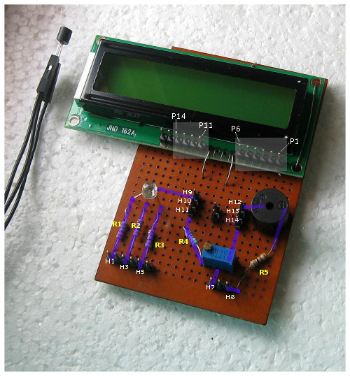
| Funboard Connector | Where to connect on Main Board | Comments |
|---|---|---|
| H1 | D10 | Cathode for Red color (via current limiting R1 = 270 Ohm) |
| H3 | D9 | Cathode for Green color (via current limiting R2 = 270 Ohm) |
| H5 | D6 | Cathode for Blue color (via current limiting R2 = 270 Ohm) |
| H7 | A2 | Analog 2 for reading Pot. Note that one end of POT is soldered to +5V rail on funboard and another to GND. I have used a current limiting resistor of 1K Ohm while connecting the Pot to play safe. |
| H8 | D5 | + pin of Buzzer. |
| P1 | H12 | GND rail of funboard. |
| P2 | H9 | VCC rail of funboard |
| P3 | GND (near Pin 13) | Grounded by connecting directly to Pin13 of mainboard. |
| P4 | D12 | |
| P5 | GND1 (near 5V pin) | Grounded by connecting to first GND pin near +5V pin on mainboard. |
| P6 | D11 | |
| P11 | D8 | |
| P12 | D4 | |
| P13 | D7 | |
| P14 | D2 | |
| H9 | P2 | Second pin on LCD as shown in diagram. |
| H10 | +Vc of LM35 | LM35 is connected to board via 3 jumper wires. Make sure to connect it properly. Reversing pins can cause heating and totally damage the sensor in no time. |
| H11 | 5V | 5V pin from mainboard is connected to header H11. This enables H10 and H9 to source 5V . (H11,H10 & H9 form kind of 5V rail.) |
| H12 | P1 | First pin of LCD. |
| H13 | GND of LM35 | |
| H14 | ||
| Vout of LM35 | A0 | Middle pin of LM35 is directly connected to A0 of mainboard via jumper wire. |
If you see properly, I have tried to make the most of the pins on Freeduino board. Typically LCD is interfaced on[12, 11, 5, 4, 3, 2] , I interfaced it on [12, 11, 8, 4, 7, 2] to free two PWM pins, one of which, I’ll use for buzzer.Also note that, I have basically tied the LCD to the PCB using holes present at side of the LCD and unused soldering pads. Let me know if you know of a better way. I have not used a POT while interfacing the LCD. Pin 3 is directly grounded and it seems to work just fine . The value of resistor connected in series with the Buzzer was experimentally determined. Select a resistor using which your buzzer makes sweetest and loudest sound.
Test program
Here is the link to “all systems test” program. The above youtube video shows my board running this same program. It is not that well written but it works!
What can you do with it !
At first look it the board looks very basic. However, if you look carefully, you will realize that there are many things you can try with this board. For example:
- There are scores of things you can do with the LCD alone. For example, I put my entire resume on LCD and created a video!
- Blinking Red, Green and Blue color. Controlling intensity of each LED via PWM and creating dynamic shades of color
- Thermometer by reading the temperature sensor
- Indicating temperature level via LEDs
- Playing ringtones/notes using the buzzer. Check out my tutorial
- Creating animated display using LEDs and buzzer
- The Pot can be used as analog switch. For example, you can write many small programs and select which one to execute using the Pot.
- The Temperature sensor can be easily replaced by any other sensor of its kind
Improving upon the design
It would be great if readers can send in their feedback. It is high time that some one creates low cost open source sheild which serves as demonstration board for Freeduino and Arduino. It may be possible to create a sheild with SMT components which includes:
- More LEDs.
- More sensors.
- Larger display.
- Switches.
Such a thing if priced righ, would go a long way in making Arduino and Freeduino popular.
References
http://arduino.cc/en/Tutorial/LiquidCrystal http://arduino.cc/playground/Main/LM35HigherResolution