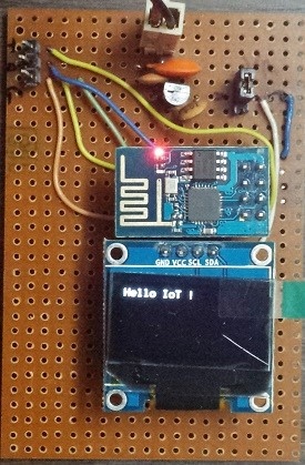
After experimenting with and reading a lot about IoT technologies, I decided to create something. So here my first IoT project: The wifi enabled portable display. This tiny little display connects to a internet over Wifi and waits for messages. It is possible to send text messages or images to the display via Internet , from your PC , mobile phone or tablet. Checkout the below video to see it in action :
Project Goals
Before we get into details, I want to go over list of goals which I had set for this project:
- Create a low cost wifi enabled display using ESP8266 and 128x64 bit OLED display. It had to be portable and battery powered.
- The display should be able to show text messages and monochrome graphics. It should automatically scroll long text messages (which cannot fit on screen).
- Create a GUI front-end which can be used with desktop or mobile browser to send images and text to the display.
- The display should handle interruptions in Wifi/Internet connection. It should automatically try to reconnect in case it gets disconnected.
- Use mostly open source tools and free stuff for software development.
High Level Design
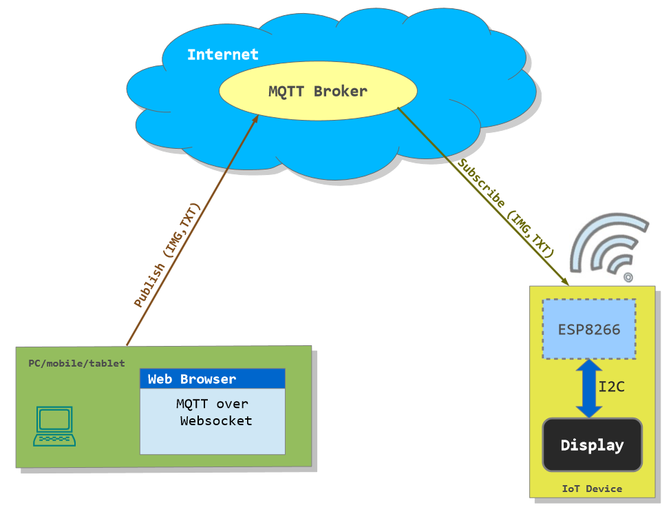
The above diagram illustrates the high level design of the project. The table given below summarizes important software and hardware design decisions
| Hardware Design | Software Design |
|---|---|
| The board consists of a single ESP8266 module which handles CPU tasks and networking. There is no microcontroller. For me the cost of all components was around USD 15 (here in India). | The ESP8266 is using the NodeMCU firmware . All the code to control the display is written in Lua. |
| I have used a 128x64 bit OLED display, which allows for displaying of descent number of characters and monochrome bitmap graphics. | To show things on OLED display, I have used the U8gLib which is available out of the box with NodeMCU firmware. |
| The display is interfaced with ESP8266 using I2C protocol. This is interesting, because we only require 2 PINs. | The MQTT protocol is used to send data to the display. The ESP8266 subscribes to a MQTT broker and listens for messages. |
| The board works on 3.3v and is mainly designed to be powered via battery. When powered by battery (6v-20v) , a 78L33 based regulator provides 3.3v . There is also the provision to bypass the regulator and provide 3.3v regulated input to board. | There is a HTML based front end , which uses Websocket to push messages over MQTT to the display. This front end has been written using AngularJs and Paho library .This makes it possible to send messages to the display using any PC or mobile device. |
| The board has PINs for serial communication with ESP8266. These can be used to modify software inside ESP8266 and debugging. | MQTT hosting provider was CloudMQTT. They have a free plan which awesome for DIY enthusiasts, really grateful to them. to try out their desigs. |
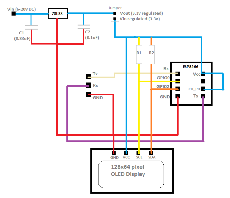
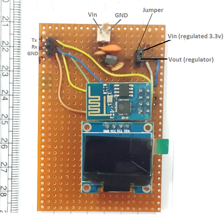
The Hardware
The hardware used for this project is very similar to what I have described in my previous article . The only difference being , there is an additonal voltage regulator circuit. I have used 78L33 regulator IC which can convert 6-20V to 3.3v(regulated) with max current of 100mA. I use four AA batteries to power the board. In my tests I have found that the circuit takes around 70-80mA, so choice if regulator is well suited for it. On the circuit board the output of voltage regulator is connected via jumper to rest of the components. The ground PIN is exposed on the board, which allows powering the board from an external 3.3v regulated source. The Tx and Rx pins of ESP8266 are also exposed, which allows for upgrading the software very easily.
The Software
This is where things get very exciting. As I have already stated, the board uses an ESP8266 with NodeMCU firmware as a CPU. This means all the code for board is written in Lua. I won’t go into details of the code in this article, you can download it from here. The most challenging part about writing the software was getting the timings correct. There are three important things which the software does, which are:
- Scrolling of text in case of long messages.
- Displaying of ‘New Message’ splash screen on receiving new message for couple of seconds.
- Executing the ‘picture loop’ of U8glib (library for interfacing the display) at regular interval.
- Checking if the board is connected to internet at regular intervals and trying to connect if disconnected.
The most challenging part was use of timers to make above actions possible (forget multithreading or fancy programing constructs !). One problem which I have not been able to overcome is , being able to read complete binary data for a 128x64 bit image. As a result, I changed the code to only accept and display 96x64 bit images. This problem could be due to speed at which my program is able to read data from socket or something to do with internal buffers. Honestly speaking, I have given up on debugging and finding a fix for this issue. With NodeMCU it is simply very time consuming and painful.
Talking to the display from Internet
Okay, so we have a display which connects to internet and waits for messages. But what good is it, if there is nobody to send a message. To address this, I have created a HTML front-end which uses Paho (MQTT over Websocket) javascript library and AngularJs . This front-end, (as shown in the video) can be used to send text and image messages to the display. I have only tested it with Chrome and IE on Windows 8, but it should work with any browser which supports File API and WebSocket.
Downloads and instructions
You can donwload the full source code here https://github.com/code2k13/WifiDisplay
Here is the list of files contained in the repository with descriptions:
| File Name | Comments |
|---|---|
| messenger.html | The GUI front-end to send messages to the display. It uses following libraries from CDN: |
| mqqtws31.js | The Paho MQTT library. Download it from their website and place in same folder as messenger.html |
| smart_lcd.lua | Contains LUA code for the hardware. Needs to be written to ESP8266 as main.lua. Please refer to my old article for details. Also do not forget to change wifi networkId/password and MQTT server details in this file (check out the header.) |
| smart_lcd_init.lua | Needs to be written to ESP8266 as init.lua. This contains 'dofile('main.lua')' statement, which executes our code when the board powers up. Here again refer to my old article on writing this file along with smart_lcd.lua to ESP8266 |
| Sample 96x64 bit monochrome bitmap images |   Right Click over the images and select 'Save ..' in your browser to save these images. |
Finally
Hope you liked reading about my first IoT project. I have learned quite a bit about IoT while making this project. This project is an excellent example of how hardware and software work together to make things work. There are many interesting things you can do with this little device, which I will be covering in future articles. As always, suggestions and feedback are always welcomed !
Thanks to:
- Makers of the Paho MQTT library:
https://github.com/eclipse/paho.mqtt.javascript - Folks working on NodeMCU:
https://github.com/nodemcu/nodemcu-firmware - Folks for creating awesome U8glib:
https://code.google.com/p/u8glib/people/list